
Can you explain what you do to the original RM, please? Was the stock chamfer added back to machined cam gear, or did you just ground down the backside?
...I said please:hsughc:
What is achieved by doing this?
follow_along_with_video_below_to_see_how_to_install_our_site_as_web_app

Note: this_feature_currently_requires_accessing_site_using_safari
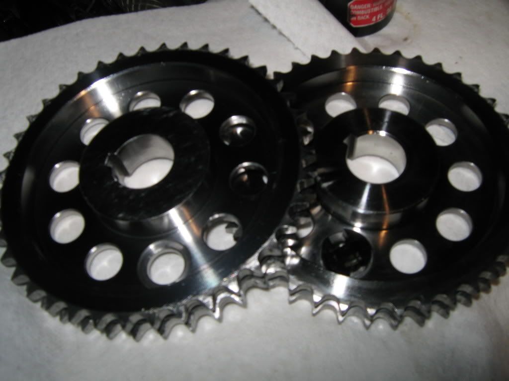
i deburr all edges including all the teeth on the cam/crank sprockets, its even more necessary since they changed to what i believe is live tooling on the cnc lathe, there is tons of metal deformation at the edges.When you take material off the backside of the cam gear to get them to align, the chamfer isn't as deep as it was prior. Like in picture above. Do you add the chamfer back to the gear or just leave it?
i havent checked these two but on ajl227's setup, his cam gear was within .0025 tir using a 1/4inch gauge pin, the worst one i ever measured was a JP dbl at almost 5 thou tirWhat is the concentric issue with the cam gear? Or is this on the JP sets?
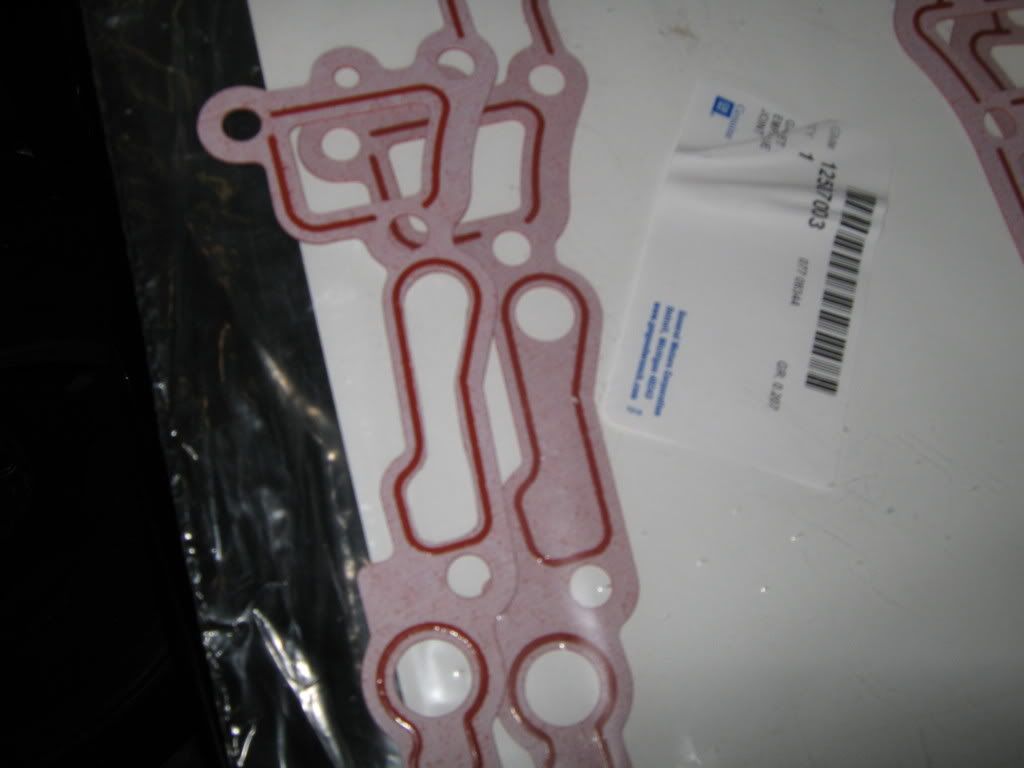
For front cover gaskets, I currently have a single felpro metal gasket sitting on the shelf; some say run 2 paper gm's due to increased thickness. Others say it increases the likely hood of leaks (double gasketing) and to run a machined pump cover and single gasket...Whats your say?
who the fuck is this guy

who the fuck is this guy
persistent enough to know he's serious about making sure his shit goes together correctly
just another fucktard mod'n turdyatehundreds
 n a junk m90 3800. Just need time and resources (thanks for the info James) to put it together. Hopefully getting around to it this coming year, but who knows my parts have been collecting dust for over a year now.


well that just adds more to the .020-.030 that ive seen on all the sets ive done.
this was with a stock cam for your rockered setup right?
well that means there's more evidence that the OEM/Comp cams require the bottom range, .020-.026
and the CamMotion/intense cams requiring the large end at .025-.030
