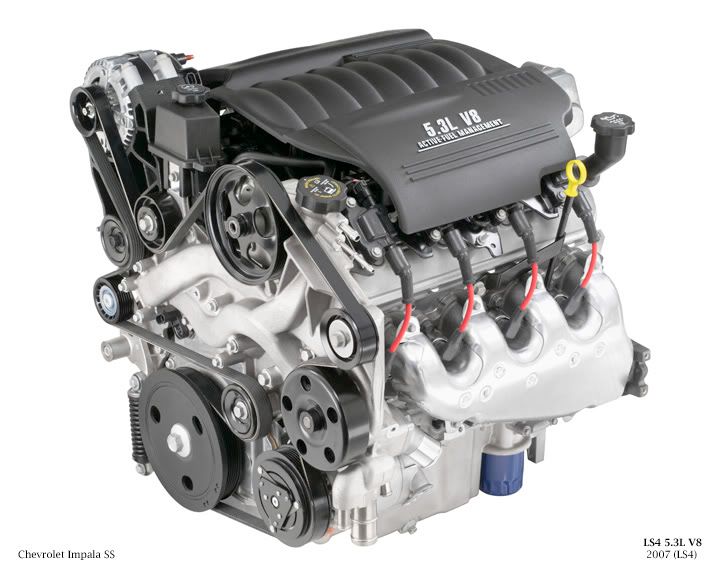
Generation IV 5.3L LS4 V8 Overview
The 5.3L LS4 shares the basic architecture of the 6.0L LS2. This includes an all aluminum block, six-bolt main bearing caps, deep-skirt cylinders, and a structural oil pan. It has the 243 casting LS6 heads with LS1 valve springs, which are good for 6200-6300 rpms.
Engineers had to mount this engine sideways so some changes were made. The crankshaft is shorten by 13 mm overall, 3 mm at the flywheel and 10 mm at the accessory drive. This was done to accommodate a more compact accessory drive. Instead of a 2 belt system there is only 1 long serpentine belt, even with this to save space there is only about 2 inches between the crankshaft pulley and the passenger side wheel well. The water pump is mounted off center with elongated passages to connect to the block (see picture). Also a rear facing intake manifold was designed. To ensure proper oiling during high-g cornering the oil pan has special baffles built in. Since Displacement on Demand uses oil for activation an oil pump with 31% more flow than previous LS2 type oil pumps is used.
Displacement: 325ci (5328cc)
Compression Ratio: 10:1 (premium fuel is recommended)
Bore x Stroke: 3.78" x 3.622" (96mm x 92mm)
Firing Order: 1-8-7-2-6-5-4-3
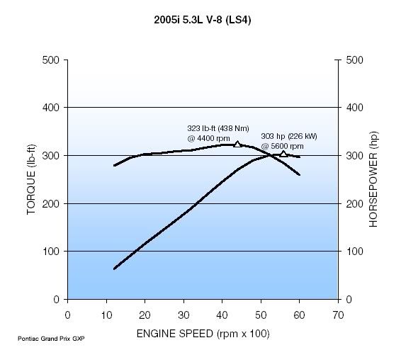
Horsepower: 303 hp @ 5600 rpm
Torque: 323 lb-ft @ 4400 rpm
Fuel Cut-off: 6100 rpm
5.3L LS4 V8
GM Dyno
Displacement on Demand (DoD) General Information
The original name was Displacement on Demand (DoD). For the start of the 2006 model year GM renamed it Active Fuel Management (AFM).
During light load conditions while in 3rd or 4th gear the ECM will shut down cylinders 1, 4, 6, and 7 to put the engine in V4 mode. The engine will
not enter V4 mode while cranking, idleing, or heavy acceleration. To shut down the cylinders the intake and exhaust valves stay closed and the fuel injectors stop feeding gas. The ECM times the shutdown so that each deactivated cylinder keeps the exhaust charge from the previous combustion cycle. This pressure on the pistons keeps them from rocking around in the cylinder causing vibration and oil consumption. Complete cylinder deactivation is accomplished in about 250 milliseconds.
The engine components involved in cylinder deactivation are the valve lifter oil manifold (VLOM) and special valve lifters. The VLOM consists of 4 solenoids that control oil flow to 8 valve lifters. Each solenoid goes with a certain cylinder and its 2 valve lifters.
When DoD is commanded on by the ECM the 4 solenoids energize and allow oil to flow to the valve lifters. The special valve lifters are made of an inner lifter and outer lifter with a spring loaded locking pin holding them together. When the oil gets to the lifters the pin is pushed out of place and the inner and outer part of the lifter are allowed to move seperately. The camshaft is still pushing on the outer part of the lifter, but the inner part of the lifter is no longer pushing up on the pushrod. This keeps the intake and exhaust valve shut permanently until the ECM commands DoD off. At this point the solenoids stop oil flow to the lifters and the spring loaded lifter pins lock back into place, causing the lifters to return to normal operation.
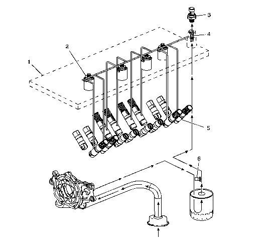
The valve lifter oil manifold assembly (1) is bolted to the top of the engine block beneath the intake manifold assembly. The oil manifold consists of four electrically operated and normally-closed solenoids (2). Each solenoid directs the flow of pressurized engine oil to the DoD intake and exhaust valve lifters (5). The oil pressure relief valve (6), located in the left rear area of the oil pan, regulates engine oil pressure to the lubrication system and the oil manifold.
When enabling conditions are met for DoD operation, the PCM will ground each solenoid control circuit in firing order sequence, allowing current to flow through the solenoid windings. With the windings energized, the solenoid valves open and direct pressurized engine oil through the manifold into eight vertical passages in the engine block lifter valley. The eight vertical passages, two per cylinder, direct pressurized oil to the valve lifter bores of the cylinders to be deactivated. When vehicle operating conditions require a return to V8 mode, the PCM will turn OFF the ground circuit for the solenoids, allowing the solenoid valves to close. When the solenoid valves are closed, remaining oil pressure is exhausted through the bleed passages of the manifold into the engine block lifter valley. The housing of the oil manifold incorporates several oil bleed passages that continually purge trapped air from the manifold and engine block.
To help control contamination within the DoD hydraulic system, a small replaceable oil filter (4) is located in the manifold oil inlet passage. The oil pressure sensor (3) monitors engine oil pressure and provides information to the PCM.
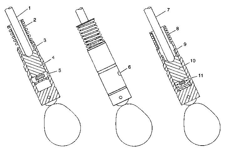
When operating in V8 mode, the DoD valve lifters function similar to the non-DoD valve lifters. The DoD oil manifold solenoids are in the closed position with no pressurized oil directed to the valve lifters. The pushrod (1) travels upward and downward to actuate the rocker arm and valve. The spring loaded locking pins (5) of the lifter are extended outward and mechanically lock the pin housing (4) to the outer body of the valve lifter (3).
When the DoD system is commanded ON, the PCM will direct the solenoids of the oil manifold to open and direct pressurized oil to the valve lifters. Oil travels through the manifold and engine block oil galleries and enters the inlet port (6) of the valve lifter.
When operating in V4 mode, pressurized oil forces the locking pins (11) inward. The pushrod (7) remains in a constant position and does not travel upward and downward. The outer body of the lifter (9) moves upward and downward independently from the pin housing (10). The valve lifter spring (8) retains tension on the valve train components to eliminate valve train noise.
When the DoD system is commanded OFF, the PCM directs the solenoids of the oil manifold to close, stopping the flow of pressurized oil to the valve lifters. The oil pressure within the lifter will decrease and the locking pins will move outward to mechanically lock the pin housing and outer body.


")